Rebuilding Emily's Wiring Harness
S2 Wiring Harness Restoration
Update: As of Jan 22, the harness has been cleaned, repaired and fully documented,
- Additional conductors have been added in anticipation of the incorporation of 4 relays and a windshield washer pump in the front trunk, and of instrument and possibly other connections to the 4AGE ECU in the engine bay.
- Some conductors have been left unterminated, pending installation in the car.
- The window motor/speaker harness is TBD, as is the hazard flasher circuit.
- The battery/starter/charging circuit wiring should be replaced, pending final arrangement.
- Next step will be to select an updated fuse box and reconfigure the wiring for greater protection, alongside replacement of the ammeter with a much simpler volt meter.
S2 Wiring Harness Restoration
This time-consuming task resulted in much of the harness being replaced or repaired, and all connections labelled.
Update: The following additions were made to the factory harness
- 3 instrument wires were run from the fascia panel to the engine bay
- TEW 16/26 yellow
- TR64 18/16 orange/white hash marks
- TR64 18/16 white/purple hash marks
- relay power wires were run from the fuse block to the front trunk near the rad. These will be fused.
- 2 runs TEW 14/41 White/Purple (for aux circuits)
- 2 runs GPT 16AWG Green/blue (for Ign circuits.)
- Windshield washer pump wire was run from fascia to the front trunk, with excess
- TR64 18/16 purple/light blue
The work involved:
Emily's wiring harness had been ravaged by time, and savaged by prior owners. To repair, it was stripped of wrapping tape, cleaned, examined and documented in detail, then painstakingly labelled, repaired and upgraded. The work was unexpectedly dirty and extremely time consuming, but was an excellent way to fully understand the car's electrical system. Every repair seemed to reveal a further repair opportunity.
The PVC insulation hardens somewhat in the hottest places, but has remained flexible elsewhere. The conductors are generally in good shape, and the main harness is mostly usable. The stock plastic tape is pretty easy to remove, however under that the harness is bundled with a cloth tape, nasty stuff with gooey stick difficult to clean adhesive. Isopropyl alcohol will clean the wire but not your hands. Wear gloves.
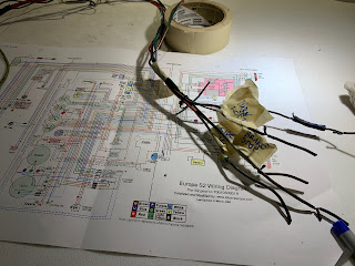
The wiring diagram located here proved essential..
http://www.lotuseuropa.org/gallery/albums/album13/s2_diagc.gif
Wiring Related
Fuses and Relays
LED lighting
4AGE ECU
Harness: Details and Overview
Wire Gauge
Wire Colour Logic
Europa wiring colour codes can be broadly grouped as follows:
Green - these are wires that are carry current to functions that operate when the ignition is turned on. They are all protected by a single fuse on the IGN side of the fuse box.
White - white, or white with stripes are involved with tbe ignition circuit or are run off the ignition feed. power is supplied via the white /red wire from the starter solenoid, through the ignition switch, to the fuse box (ign section) and tach.. This white feed, powers the green wires via the fuse block. Additionally, the Oil idiot light is WB. Engine related?
Brown - these are the main unswitched unfused power feeds, they are supplied from the battery/starter alternator, to the ammeter, thence to branch circuits or those related to charging.. The power windows are powered by a brown wire and the circuit is always live and are unfused. (fire escape?) The light circuit is powered by a brown wire from the ammeter and is unfused.
Red - red wires are typically controlled by the light switch. Unless they are speakers.
Purple - purple wires connect the rad fan and the convenience lights, and are on the fused, auxiliary circuit which is not controlled by the ignition switch. Just like the brown wire on the window motor harness.
Black - grounds.
Blue - These are switched items in the front of the car, headlights and wipers.
Green/blue, blue/green, light green/blue etc - Sensors and misc -
Terminations
Ring and Tab terminals
In many places rings and .250" tab/faston terminations are used. These are standard types and widely available.
Bullet Terminals
The Male bullet terminals on Emily's harness measure .182”/4.63mm in diameter. A quick search finds reference to 4.7mm(.185”) for older British cars. There are also M4, M5 listed, I would assume these are 4mm and 5mm. The readily available size in Canada is .156”, with .180” listed in some places.These are not highly precise connectors by design. The .180" female connectors available locally are within .002" of the originals, and seem to be more robust. Though nominally larger, they seem to have a higher retention force.
Harness Documentation
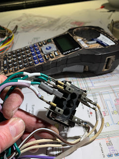
What follows summarizes the process of cleaning, inspecting, repairing and labelling 54/1871s wiring harness. I began with the taillight section and worked my way forward, referring to the colourized and unbelievably helpful diagram posted on lotuseuropa.org. I printed the file onto a sheet of ledger-sized paper and donned my magnifying glasses and had at it. It took around 9 hours on a freezing cold Sunday, to get started, during the height of the omicron wave to clean it up and identify the issues. Several more hours (and counting) to rectify them. I would estimate it will take around 25 hours to finish, with some final work to be done upon installation.
Rear lateral section (taillights, license plate, reverse switch
The harness branch itself contains:
- Green (G)– power from fuse block to remotely switched circuits – reverse and stop lights.
- Green/Violet (GP) – power from brake switch to brake lights, energized by switch.
- Green/White (GW) – power from turn signal switch, energized by right turn switch.
- Green/Red (GR)- power from turn signal switch, energized by left turn switch
- Red (R) – powered by the light switch and connected at a multi-way bullet connector behind dash , this feeds the tail lights. (indicator) and other switched lighting circuits.
- Black (B) – ground which terminates at the voltage regulator in the engine bay.
- Left taillight
- COMPLETE - all items below addressed. wires at the tailights will need to be reterminated, and license plate light connections made/
- wires were cut and poorly spliced, likely too short. One red wire had been spliced at the license plate junction and replaced with a length of green. This needs replacement. need to confirm wiring at light housings.
- License plate
- As noted above left taillight red wire (currently green) needs to be replaced.
- Bullet connectored Pigtails for license plate light need replacement. Area seems to be intact
- Broken contact from license plate light itself evident. This light requires replacement.
- Reverse switch
- Intact at switch junction however a length of red wire was poorly spliced into the section between the switch and left rear indicator. Replace.
- A ground seems to have been added between the reverse switch and bullet junction at the license plate. Redundant.
- Right taillight.
- Remarkably intact, one bad splice at reverse light.
Engine Bay
The rear section is one branch of a multi branch junction at the engine bay. This junction includes the coil, alternator, main relay, regulator, distributor and the carb shut off solenoid..
- Ignition coil/carb These are small sections within the harness that are worn and will not likely be required for the 4age
- Two white wires from a single ring terminal are intact however the insulation on one is cut. One connects to the tach, the other is intended for the carb shut off solenoid. (not required)
- A second white wire emerges with a later addition of a faston terminal – likely the carb shut off solenoid connection, which will probably not be required and was likely severed when the TC engine was installed.
- A white/black wire from the coil had excess length folded into the harness bundle and connects to the “ignition” (distributor points) . Its ring terminal is about to fall off due to broken strands. This wire should be replaced as it lives in a hot area and is stiff, and has a spliced length at the distributor end. It will be redundant with the 4age addition.
- There is insulation chafe evident inside the harness bundle. tape or replace chafed areas if not the entire length.
- Alternator bundle
- The original heavy gauge Brown/White ((NW) and Black (B) wires are present along with the normal gauge Brown/Green (NG) which connects to the voltage regulator. The original purpose of this white wire needs to be determined and if required, it should be replaced. The charging circuit will need to be revised for the 4AGE installation, and its internally regulated, higher output alternator.. This bundle will likely be replaced with a simple connection to the battery.
- Voltage regulator bundle
- Mid-gauge brown white is present but insulation is chafed. Tape or replace. Light gauge brown/green is present. Two ground wires, one mid gauge one light terminating in a single ring likely belong with this bundle. The charging circuit will need to be revised for the 4AGE installation.
Future connections, for an internally regulated alternator.
Working forward, Various grounds converge at this point.
- Grounds
- A grounding strategy is a worthwhile consideration here. The light gauge wire from the chassis ground to the interior light is damaged and a new length should be added. The heavier wires are quite stiff (heat?) and should be replaced. This
- Starter
- The two expected brown wires (N) converge in a single ring terminal here, These are stiff and tired at the ring. A start relay should be added, and these wires replaced as they are the main currenty carrying conductors. A third red wire was found in the bundle, replacing the white/red (WR) wire from the ignition key in the diagram. (found melted elsewhere in the harness.) this was replaced with the correct colour code WR, but a much heavier 12 AWG wire. A start relay should be added as should fusing to protect the wires that feed the fuse block and the ammeter. This is detailed here.
- Distributor
- the white/black (WB) wire which connects the points to the coil (above) exits here to connect to the distributor. This wire is quite stiff and should be replaced
- Oil Light
- There is a severed white/brown WN wire exits the harness bundle at this location. (with the distributor wire.) The insulation is stiff in the engine bay area and this section should be renewed.
- Stop switch
- Complete
- I marked this “brake T” when I removed it from the car.
- There were some strange owner mods to this, not sure why. See the pic below of the
- The two green wires converging in a single 90 deg faston terminal are present. This has been butt spliced at some point and requires repair A new length of wire was spliced into the harness.
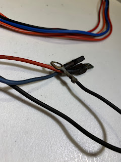
- The Green/violet (GP) wire is present, this energizes the stop lights when the brake switch is closed. There were some strange owner mods to this, not sure why. See the pic below of the crimp on 3 way lug. This was removed, the wires replaced where required and re-terminated and labeled The wire is labelled, and the colour code maintained with a violet Sharpie.


The next wires exit together near the termination of the oil pressure tube..
- Oil Pressure
- this light green//Blue (LGU) wire was damaged with sections removed so all remaining sections were removed. The 4AGE uses a single oil pressure wire so this wire should be replaced. (three new wires were added for future instrumentation requirements)
- Fuel tank
- Complete
- wires are present and intact but are very stiff near the sender terminals. Replace last few inches. approximately 24" of both wires was spliced into the harness, and re-terminated and labelled.
- Temp Sensor
- only short lengths of severed Green/Blue GU wire were found (and were removed) (three new wires were added for future instrumentation requirements)
- Interior lamp
- Complete
- This is as expected except the colour code is Violet/white (PW) where the schematic indicates PB. Insulation is appears melted on the violet wire between the interior lamp and the fuse panel. the lens on the interior lamp is also melted.. The dome l This wire was replaced with a 16AWG wire of the correct colour code, from the light connection to the fuse block.
After this point the harness continues in excellent condition and without branches until
it meets the fascia. The wires present
are:
Light gauge (between 18-20 AWG)
- Green/Red (GR) left indicator
- Green/White (GW) Right indicator
- Green/Black (GB) Fuel Tank
- Green (G) power to stop switch and reverse switch)
- White/Brown (WU) orphan identified above
- 2 ea White (W) both to coil.
- Violet (P) interior lamp
- Violet/White (PW) interior lamp
- Red (R) indicator lamps. This should run to double connector near light switch and ammeter
Med gauge
- Red (R) mentioned earlier under starter – this is a replacement of a burnt wire, from the ignition to the start relay, indicated as WR in the schematic
Heavy Gauge
- Brown (N) from starter to ammeter This should be replaced and run to the fuse block.
- Brown/White (NW) from alternator (to ammeter) This should be removed.
At the fascia, the front of car, Fascia/steering column sections converge. This is also the location of the fuse block. I disconnected the power
window sub harness from the fuse box so there is less of a tangle, the other two
branches cannot be separated.
Fascia (Dashboard) Branch
Here I also discovered some stories…
I located a burnt, heavier gauge WR wire at the junction. (remains were removed) This had been replaced by the
red wire discussed above, which leads to the ignition switch . There are also two severed wires at the same
location, on GU*, one LGU **. It appears that the TC engine swap caused the
oil pressure and temperature circuits to be removed or modified. I removed the remaining sections of those wires.
· The ground wires in the fasica show some damage. The chain connecting the gauges to the heater switch and fascia ground were cleaned and one faston re-terminated to incorporate a lead for fascia ground. This had been a twisted jury rig by the PO, pictured below.
- Fuel gauge
- Complete Green/light green (GLG) and green (G) wires present and are now marked.
- Temp
- Green/Light green (GLG) and Green/Blue(GU) wires present but severed, and and GU is the wire referred to above*. o What is the story with the temp gauge? It appears this and OP were disconnected with TC install.
- Ignition switch
- Complete
- One wire broken off, as noted WR wire replaced with R. Red (WR) 2ea W, and NW all present. Connection to radio absent. Wires were replaced as required, WR colour code respected, re-terminated and labeled.
- Heat switch
- Complete
- GY, RB and B all present. RB was reterinted, wires labelled, associated ground harness segment repaired .
- courtesy switch
- PW wires both evident, wire in GC however Drivers'side female bullet conn needs replacement.
- Ammeter
- All brown wires evident.
- Appears that oil pressure gauge wires severed in this bundle (G, LGU) This is the LGU wire discussed earlier.**
- Oil pressure.
- Complete - 3 wires added for instruments.
- The wires to this gauge have been severed, however a tube may have replaced them with the TC swap
- Wiper Switch
- Complete. Terminations renewed, wires labeled. Additional wire added to front trunk for electric washer pump.
- Brown/lt green (NLG), Red/Lt Green (RLG), Blue/light green (ULG) and 2 ea green wires present. Need to be reterminated. Pump pressurizes however plastic mounting threads stripped.
- Can the wiper switch be replaced?
- Blue wire and pull switch was added. (removed Washer pump This was poorly done and green wires need to be reterminated.
- Light switch
- Complete.
- Brown, brown/red, brown/blue all in good shape. Red multi-way bullet for other joints present.
- Two wires, likely for front and rear indicator lights, exit the harness here. These connect to a multi-way bullet junction, which is present.
- Idiot lights, instrument lights.
- Complete
- Oil, high beam (“main”), and turn signal all present, and as is Green wire with multi way bullet connector.
- Are LED replacements available?
- All seem present along with ground harness.
- Steering Column
- Complete
- Clean, labelled and looking good!
Next branch leads past the fuse box to the front of the
car. Other than the window switch wiring
harness, I left the fuse box connected.
Fuse Block
These wires need to be labelled, and a fusing strategy determined.
Front of Car
- Wiper motor connector.
- Green wire is not secure in molded connector. This should be addressed.
There are 11 wires that are bundled, leading to the front of the car. There were two owner additions which I had labelled “brake T” and “Wash”, along with a length of vinyl hose from the windshield washer. These ran in parallel to the main body of the harness. They have been binned. The harness branches in the front compartment, Another owner addition was removed, it had been labelled “fan”.
- Thermal rad fan switch
- This was intact with three black wires. The heat shrink had hardened and was removed to inspect the terminations, which are sound. This heatshrink should be replaced with clear upon reassembly, once the termination style of the new switch is confirmed.
- Fan Motor and relay
- This is intact but needs terminations replaced and a 2 way connector added to branch the purple aux wire to provide power to the horn.
- This bundle will likely incorporate power to relays which will be used in the future.
- Horn
- This was butchered with a poor splice added to power the horn from a green ignition circuit rather than the purple.
- The splice should be eliminated and a relay used, the horn and vent fan could share a feed.
- Vent fan
- This was mess up as well. This, the headlights and the horn should probably use a relay
- Headlights and indicators
- The correct wires feeding these circuits are present and intact, however where the harness branches into the two sides only the headlamp circuits are present. There appears to have been no headlamp relay, though the harness was altered significantly.
- The indicator and side lights are not connected though the correct feed conductors are present. The feed conductors are in good condition.
- In future the headlights will be powered by two relays, one to energize a second which selects between main and dip. Thus, the headlight conductors will terminate at the relay point. These have been labelled at that point.
- Need to rewire from the main harness feed to the turnsignal/running lights and the headlights.s
Speakers and window motor harness
This is a separate harness from the main one, and I was surprised when mine did not match the drawing. The drawing shows both the speakers and window motors as having the same RW and RB colour code which seems unlikely in the same harness. pics below show Blue black red wiring of the window motors, and the damage to one side where the wires flex at the doors.




Comments
Post a Comment